QPSK demodulation
Demodulation of a QPSK signal in software is not too complicated once you've got the building blocks down. The problem is that information is very sparse, and some of the websites that had useful info about the demodulation process are no longer online. To help others build their own demodulators, here's an overview of how to go about writing a demodulator.
If you want to tag along, I'll be referencing the source code of meteor_demod when discussing implementation details, so feel free to check it out.
Signal processing overview
QPSK stands for Quadrature Phase Shift Keying, and is a digital modulation scheme that uses phase shifts of the carrier to convey data information. The goal of demodulation is to recover the bits encoded in the signal, and there are two macro-steps in this process.
First, we need to reconstruct the carrier locally, without any phase shifts, so that we can compare it to what we're receiving and identify where phase shifts happen; the output of this stage will be a "phase difference" signal.
Secondly, we have to sample the phase difference signal at the right time: the carrier doesn't jump from one phase shift to another abruptly, but does so gradually due to filters used during transmission. To have the highest signal-to-noise ratio (SNR), we have to identify the best times to sample at.
Constellation diagram
A very useful representation when discussing phase modulation schemes is the constellation diagram. If you've used meteor_demod or the QPSK demodulation plugin in SDRSharp, you're probably familiar with it: a square box divided into four quadrants, with multiple dots in it:
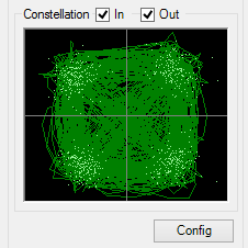
Each dot in the diagram represents a sample. Samples have two components, usually called I and Q, and they are plotted on an x-y plane based on the values of these components. The QPSK modulation scheme assigns one bit to each components, so that each sample carries two bits. For example, if the two bits to transmit are 1 and 0, I might be maximum positive and Q maximum negative, resulting in a dot in the bottom-right quadrant.
When debugging a demodulator, you may come across the following cases when plotting the symbols at the output:
- The points in the diagram have seemingly no structure. This means that both the symbol timing recovery and the carrier recovery are not locked, or not working.
- The diagram shows a square with the diagonals. In this case, the carrier is properly acquired, but the symbol timing recovery is not working properly.
- The diagram shows a circle, with very few to no points in the middle. This happens when the symbol timing recovery is working, but the carrier recovery is not.
- The diagram shows four clusters of points, one for each quadrant. This is the end goal, where both the carrier recovery and the symbol timing recovery are working correctly.
Step 0: filtering
Every signal propagated in the atmosphere is subject to noise. While it's impossible to eliminate it completely, it can be attenuated by filtering only the range of frequencies we're interested in.
The type of filter used by Meteor-M2 is a Raised Cosine filter, which has the nice property of zero inter-symbol interference (adjacent symbols are not smeared together). Half of it is applied at the transmitter side, and the other half has to be implemented at the receive side. The half of the filter we have to implement is known as Root Raised Cosine filter (RRC).
The ideal filter has an impulse response with tails that extend to infinity, but that's not really implementable in software, so a finite-response approximation is used. The received signal is then convolved with the approximated filter, and the output used for further processing. To put it simply, convolution multiplies each input sample by all coefficients in the filter, shifts the resulting array by the index of the sample being considered, and adds the resulting arrays together, like this:
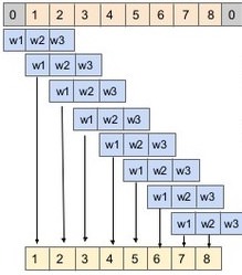
The way this is implemented in meteor_demod is by storing the last n samples in an array, and when a sample is requested from the filter, it is computed on the fly. Same working principle, just more efficient because many samples are discarded anyway, so their computation is not necessary.
Another concept that is combined is that of polyphase filtering to increase the sample rate. In order to recover the clock as accurately as possible, the sampling rate should be as high as possible. Using a very high sampling rate throughout the signal processing chain would slow everything down however, so the signal is artificially upsampled during the filtering step. The coefficients are computed for a filter with sampling frequency k times higher, and they are split into k filters with n coefficients each. The appropriate phase is then picked by the symbol timing recovery algorithm, resulting in both excellent filtering performance and low processing times (dsp/filter.c).
Step 1: automatic gain control
In a perfect world, the signal received would not only be unaffected by noise, but also have constant amplitude. This is not the case, so for the demodulator to work at its best it should also amplify the signal dynamically so that its amplitude is more or less constant for the entire duration of the pass. There are many ways to achieve this, but in meteor_demod each sample is multiplied by a gain value, which is adjusted so that the magnitude of the samples received is, on average, close to an arbitrary target value of 190 (dsp/agc.c).
Step 2: carrier recovery
Once we have a nice, clean-ish signal, it's time to find a carrier inside of it, and lock on to it to identify phase shifts. For QPSK signals, this is done with a Costas loop, which is able to tune a local oscillator to match the frequency of the carrier regardless of the phase shifts present in it.
The way a Costas loop works is fairly simple: look at the difference between the local oscillator and the carrier we're receiving, and adjust the local oscillator's frequency and phase so that it's closer to the received signal. This is the typical use case of a digital control loop: given a (noisy) error signal, adjust some external system (the local oscillator) so that the error signal is reduced to zero over time. The parameters of the control loop are adjusted to have a quick response, but at the same not be too susceptible to noise on the input.
As mentioned, the main complication introduced by the QPSK modulation scheme is that we cannot just look at the carrier and try to lock on to it, because its phase changes based on the input data. The Costas loop solves the issue by cross-multiplying the I and Q components with their signs (a.k.a the bits they encode). To put it another way, the Costas loop classifies each symbol on the input in one of the four quadrants, and tries to align the local oscillator so that its output is closer to the nearest diagonal. The relevant file in meteor_demod is dsp/pll.c.
Step 3: symbol timing recovery
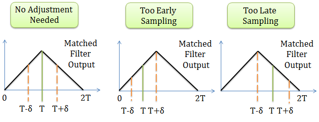
The last step to obtain the encoded data is to sample the phase signal from the Costas loop at the correct time. The rate at which symbols are transmitted is known (72ksym/s or 80ksym/s are typical for Meteor-M2), but sampling at the wrong time will result in sub-optimal SNR. If we sample too early or too late, the magnitude of the signal will be lower than ideal:
There are multiple algorithms to recover the exact symbol timings, each with different properties. Some can work before carrier recovery is performed (Gardner), others require carrier synchronization to work properly (Mueller & Muller). More info about each one can be found here.
The algorithm implemented in meteor_demod is the modified Mueller & Muller for generic M-PSK modulation schemes (dsp/timing.c), because it can also compensate for slight symbol frequency discrepancies, which might be introduced by rounding errors.
The working principle is similar to the one described for phase recovery: an error signal is derived from symbol amplitudes, filtered, and then used to tweak the local symbol clock, so that it matches up with the symbols that are received from the satellite.
Odds and ends: OQPSK
While the official specification from MetOp specifies the modulation scheme as QPSK, we've seen at least one satellite from the Meteor-M series use an alternative scheme: Offset Quadrature Phase Shift Keying, or OQPSK. The difference is that the transitions of the Q component are delayed by half a symbol period compared to the I component. This only slightly changes the demodulation process: the two components have to be sampled separately, as mentioned, half a symbol's period apart. The rest of the demodulation is unchanged.